Tcm Readiness Code Must Be Generated Again
Parlé-series Beamtracking Microphones
The post-obit article provides information virtually Biamp's Parlé-serial Beamtracking™ Microphones. It discusses some of the core technologies that make these microphones work, likewise every bit the resource available in software for setup and configuration.
Hardware overview
| TCM-X | Plenum network box + one ceiling-mount microphone array |
| TCM-XA | Plenum network box with built-in amplifier + one ceiling-mount microphone array |
| TCM-XEX | Ane expansion ceiling-mountain microphone array |
| TTM-X | Under-table network box + one tabletop microphone array |
| TTM-XEX | One expansion tabletop microphone assortment |
| TCM-one | Plenum network box + 1 microphone array pendant |
| TCM-1A | Plenum network box with built-in amplifier + one microphone array pendant |
| TCM-1EX | Extension plenum network box + one microphone array pendant |
Topology
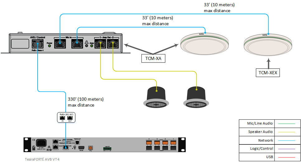
TCM-XA/TCM-XEX/TCM-X
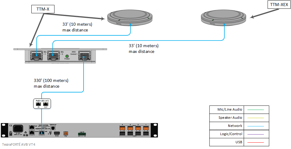
TTM-X/TTM-XEX
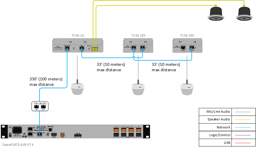
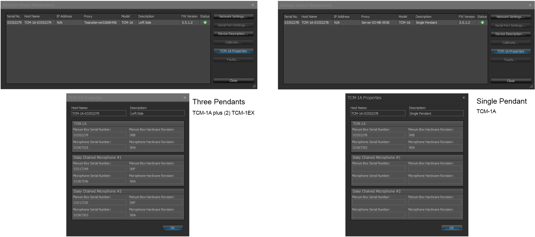
TCM-1A/TCM-ane/TCM-1EX
Cabling
Each TCM-one or TCM-1A tin host up to two TCM-1EX extension microphones continued in a daisy chain using standard CAT5 or meliorate cable. This ways that, with only a single cable run from the ceiling down to the DSP, yous tin have coverage from three beamtracking microphone arrays, which should exist suitable for nearly minor to mid-sized briefing room applications.* The TCM-10 and TTM-Ten have a slightly different topology. Each AVB network box supports upwardly to two microphone arrays. So you can utilize one TCM-Ten (or TCM-XA) and add a single TCM-XEX expansion microphone array to the same network box. The same applies to the TTM-X and TTM-XEX.
There is a maximum distance of 330' (100 meters) between whatever network box and the AVB capable network switch. Point-to-point cabling betwixt the TCM-1 / TCM-1A and the first TCM-1EX has a limitation of 33' (10 meters). Indicate-to-point cabling between the first and 2nd TCM-1EX units also has a limitation of 33' (ten meters). In all models, the supplied pendant microphone allows a maximum drop of 10 anxiety (3 meters) including any strain relief within the plenum ceiling box. TCM-i pendants are available in white or blackness.
The maximum distance betwixt the network box and microphone array for the TCM-X, TCM-XEX, TTM-X, or TTM-XEX is 33' (ten meters). Note that this total altitude includes the six.5' (2 meter) cablevision provided with the TTM table tiptop microphone array. The TTM cablevision tin be extended a maximum of 26.v' (eight meters) beyond the included cable. The cable can be extended with an RJ-45 coupler and boosted CAT cablevision.
* When installed at a acme of 8' (ii.5 meters), the Parlé Beamtracking Microphone maintains a STIPA A rating over a coverage diameter of sixteen' (5 meters). Room conditions at time of measurement: RT60 (@5meters) = 425ms, Noise Flooring weighted (at the microphone) = 38dBSPL-A.
Integration of TCM-1A with Desono C-IC6
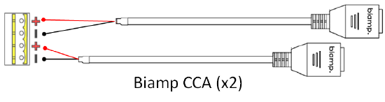
In addition to integration with amplifiers that apply Biamp's RJ45 speaker connection, the Biamp Category Cablevision Adapter can also be used to let for an additional wiring option when using Desono C-IC6 speakers with the TCM-1A amplifier. The Desono C-IC6 utilizes both RJ45 and Euroblock connections for versatility making connectivity via CAT5 or conventional speaker cable available. Connectivity via CAT5 cabling simplifies field termination and install time. Verify the provided Euroblock connector wiring matches with manufacture pinout for the amplifier. The adapter may as well be used with the output connector that is provided with the amplifier every bit a single or dual connectedness as shown in the diagram below utilizing a pair of Category Cable Adapters. Adapters are rated for up to 300V load.
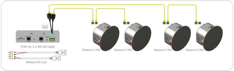
Additionally, the Category Cable Adapter can be used to connect the RJ45 ports of a TCM-XA to a generic speaker that does non have RJ45 ports.
Device Power
Each network box receives ability over the Ethernet connexion. The power requirements of each device are every bit follows:
| TCM-X | PoE (IEEE 802.3at Class 3, 15.4W) |
| TCM-XA | PoE+ (IEEE 802.3at Grade 4, 30W) |
| TCM-XEX | Powered from network box included with TCM-X or TCM-XA |
| TTM-X | PoE (IEEE 802.3at Class 3, xv.4W) |
| TTM-XEX | Powered from network box included with TTM-X |
| TCM-one | PoE (IEEE 802.3at Class 3, 15.4W) |
| TCM-1A | PoE+ (IEEE 802.3at Course four, 30W) |
| TCM-1EX | Daisy chained from TCM-1 or TCM-1A, power provided past host TCM-1 or TCM-1A |
Network boxes may exist directly connected to the AVB port on a Tesira server class device using a PoE+ injector, or via a PoE+ port on an AVB capable network switch.
Core technologies
 Beamforming is the ability to shape or steer a microphone array's directivity (or polar) design. Consider the situation where you have multiple microphones in a room, or in this case, multiple elements in an assortment. Sound volition get in at each microphone with a dissimilar fourth dimension delay and level disuse.
By utilizing DSP, we can shape the pickup pattern by compensating for the delay and level differences between microphones. A single TCM-i pendant has 8 microphone elements working together to create three 120° zones, each with its ain steerable beam. This allows for a total 360° of coverage. A unmarried TCM-Ten or TTM-X microphone array has 16 microphone elements to create four 90° zones with the same steering ability.
This is all well and adept, but beamforming is null new, and there are plenty of other microphones out there utilizing this technology. What makes the Parlé series unique is that the microphones use beamtracking technology to clarify the signals from each microphone element in order to determine where the talker is, then passes that information on to the beamforming algorithm to tell it where to steer the polar design. This is achieved, in part, by a process chosen Vocalism Activity Tracking.
Vocalisation Activity Tracking
When a bespeak enters the Parlé microphone array, it diverges into two paths: the audio signal that is sent over AVB to the Tesira server-class device, and a signal used for tracking. The tracking algorithm makes use of aggressive dissonance cancelation to ensure that racket sources in a room, such as ceiling mounted projectors and HVAC systems, do not cause the tracker to falsely trigger.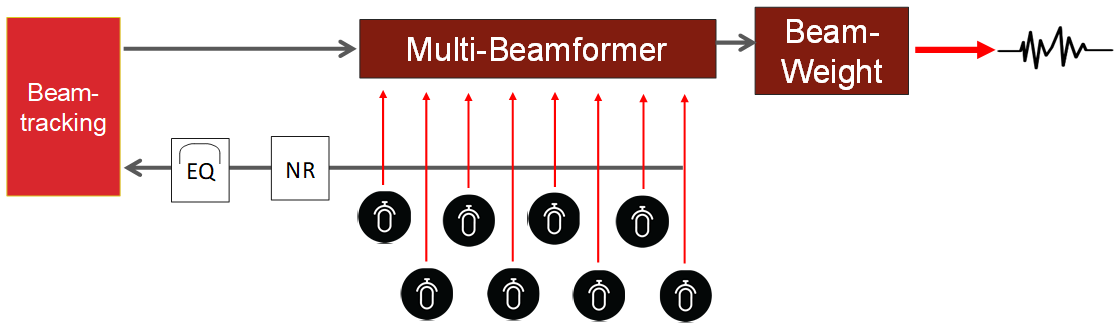
Parlé microphone arrays are optimized to only rail signals inside the frequency domain of human speech,empowering the tracking algorithm to give greaterfocus to focus on talkers in the room. It then passes this data on to the beamformer, which directs its polar pattern to the located talker.
The tracker will follow in both azimuth (left-right) and elevation (up-down) angles and volition work independently in each of the available zones.
Axle Weighting
Adding tracking capabilities to the beamforming microphone array creates a trouble for us to solve. If ii beams in a single pendant track to the aforementioned talker, such as may occur if that person is positioned between two coverage zones, it could innovate comb filtering or other phasing issues. To combat this, we implemented the concept of axle weighting. When ii beams are directed toward the same talker, each signal is analyzed and merely the stronger signal will exist selected to pass through to the remainder of the signal chain.
Beam weighting prevents phasing problems that could occur from 2 beams tracking to the same signal. However, when the signals are dissimilar, such as when two people are talking, it does not end multiple beams from being used to properly selection up talkers across multiple coverage zones. This processing takes place within the network box.
Intelligent Mixing
 Beam weighting addresses the issue of a single talker being covered by multiple beams in a single microphone assortment, merely what about a unmarried talker beingness covered by beams from multiple microphone arrays? For this, we introduced the concept of Intelligent Mixing.
If there are two microphone arrays in a room, they will both track to a man vocalism source. Intelligent mixing, which occurs post-tracking algorithm, allows the organisation to identify which pendant has the better betoken and deliver that to the final mix. This only applies to a mutual source. With separate signals in a room, multiple microphone arrays can still exist active.
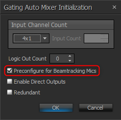
Intelligent Mixing for beamtracking microphones is enabled within the Gating Auto Mixer block when adding it to the Tesira layout file. In the Gating Auto  Mixer initialization dialog, select "Preconfigure for Beamtracking Mics." This will optimize the auto mixer settings for use with the Parlé-serial microphones. The lower-righthand corner of the Gating Car Mixer volition prove "BT" every bit a visual indication that this option has been chosen.
AEC Interaction
Biamp'due south Beamtracking Microphones are ultimately designed with conferencing and collaboration in mind, and you cannot talk about conferencing without mentioning Acoustic Echo Cancellation (AEC). AEC performance is one of the near -- if not the nearly -- disquisitional processing components in an sound conferencing organisation. Because Biamp has created both the beamtracking and AEC algorithms within Tesira, both are aware of and communicate with each other to assist ensure a quality meeting experience.
One channel of AEC processing is required for each Parle microphone input. A TCM-10 and a TCM-EX would require 2 channels of AEC (one per microphone). A TCM-i with 2x TCM-1EX would require 3 channels of AEC (i per pendant).
When the far end talks, a beamtracking microphone will analyze this point, identify it as human speech, and want to track to information technology. Nonetheless, our AEC algorithm is capable of telling the beamtracker that it is the far terminate who is talking. This volition temporarily lock the beams in place, preventing them from tracking to the far cease phonation coming out of the room'southward loudspeakers.
This interaction between our AEC and beamtracking algorithms is patented engineering science that allows for the requirement of only a single channel of AEC per microphone array. This scenario would typically require three channels of AEC (one for each axle or coverage zone).
Software and programming
Adding Biamp Beamtracking Microphones to a layout is a simple process and resource take been provided to help in the configuration. Beneath, nosotros volition highlight the blocks that should exist included when programming the layout, as well as the options available to optimize settings for use with Parlé microphones.
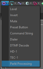
Parlé I/O Blocks
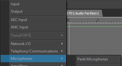
Parlé microphones are added to the configuration from the I/O Blocks listing found nether the Sound Object Bar.
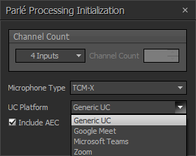
In one case the advisable model is selected and added to your layout, an initialization dialog volition be shown.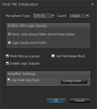 This allows you lot to configure the following:
- Microphone Blazon (TCM-one, TCM-1A, TCM-X, TCM-XA, or TTM-X)
- Microphone Count (depending on the number of total microphone arrays connected to the network box)**
- Logic Inputs for LED command and muting
- Mute options for multiple microphones as a grouping, or individually
- Enable logic outputs that could be used to drive logic functions within Tesira based on mic mute country
- Enable private axle outputs (TCM-X, TCM-XA, TTM-X only)
- Add or remove the amp block when utilizing the TCM-1A or TCM-XA congenital in amplifier
** TCM-1 and TCM-1A allow a maximum microphone count of iii. TCM-Ten, TCM-XA, TTM-X allow a maximum microphone count of 2.
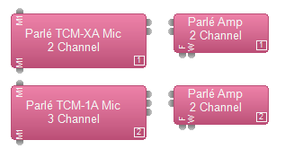
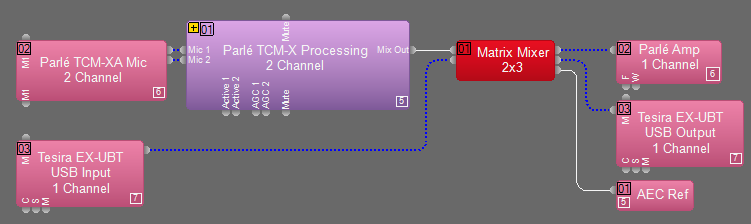
Subsequently confirming the configuration and selecting OK, the blocks volition be added to the layout. For example, choosing a TCM-XA with a microphone count of 2, a TCM-1A with a microphone count of iii, each with an amplifier included, will add the following blocks to the layout:
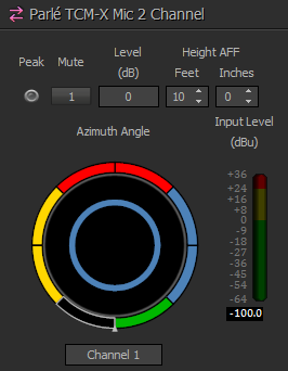
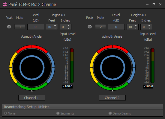 The Command Dialog for the Parlé Input cake volition display based on the number of microphones called. A software representation of the azimuth tracker will be included for each microphone, likewise as mute, level, meridian settings, and an RMS meter.
When connected alive to the system, the azimuth tracker will display an indicator for each axle or coverage zone, and will provide feedback for activity and tracking within that zone. The TCM-X and TTM-Ten microphone arrays will testify a carmine, green, blue, and yellow indicator to represent the four available beams. The TCM-one microphone array will show a scarlet, dark-green, and blue indicator to represent the 3 bachelor beams.
The tiptop should be set at the measured distance from floor to microphone array. This will affect the maximum upwards angle at which the microphone will track. A higher setting will limit the bending, keeping the beam from tracking too shut to sources coming from the ceiling. A lower setting will increase the coverage angle to adjust talkers being nearer to the mic's 0° elevation angle.
Acme In a higher place Floor (AFF) vs. Tracking Angles
| TCM-X | ||
|---|---|---|
| Pinnacle AFF | Min Elevation Tracking Angle | Max Tiptop Tracking Bending |
| < three.65 k (12 ft) | 15° | 75° |
| 3.65 m (12 ft) | 22.five° | 75° |
| iv.xv k (13.6 ft) | xxx° | 75° |
| 4.65 m (fifteen.iii ft) | 37.5° | 75° |
| 5.05 chiliad (sixteen.6 ft) | 45° | 75° |
| 5.45 m (17.9 ft) | 52.5° | 75° |
| TCM-1 | ||
|---|---|---|
| Top AFF | Min Elevation Tracking Angle | Max Elevation Tracking Angle |
| < one.five thousand (5 ft) | 0° | 15° |
| one.v m (5 ft) | 0° | 30° |
| 1.7 m (5.6 ft) | 0° | 45° |
| 2 m (vi.6 ft) | 0° | 60° |
| 2.1 thousand (six.9 ft) | 0° | 75° |
| 3.2 m (ten.5 ft) | 15° | 75° |
| 4.2 k (13.viii ft) | 30° | 75° |
| five.i m (xvi.7 ft) | 45° | 75° |
AEC Processing Block
In most cases, a Parlé microphone input volition first be connected to an AEC processing block.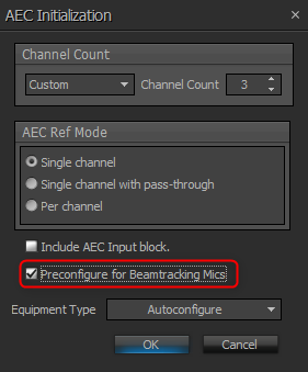 The recommended configuration for the AEC processing block when used in conjunction with a Biamp Beamtracking Microphone is as follows:
NLP = Medium
Noise Reduction = Depression
AGC = Bypassed
To quickly deploy these settings, a "Preconfigure for Beamtracking Mics" pick has been added to the AEC initialization dialog. The most disquisitional of these settings is to ensure that AGC is bypassed. When utilizing beamtracking microphones, we want AGC to occur post-automixer. This AGC processing volition be included automatically when adding the Parlé custom processing cake to the layout.
One aqueduct of AEC is required per Parlé microphone.
Parlé Processing Cake
 In an effort to simplify setup and deployment, Tesira software (3.xiv and later) includes the Parlé Processing Block that is pre-configured with the optimized DSP processing concatenation for the Parlé series microphones. This will reduce programming time and ensure that recommended steps and settings are followed when including Parlé microphones in your layout. Each Parlé Block will vary by the number of channels, only contain the same processing blocks and a single mixed output.
The block includes presets optimized for various room acoustic atmospheric condition. Refer to the Parlé Processing Block article for additional details.
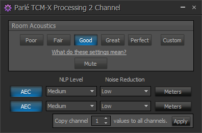
The Room Acoustics presets accept been tailored to meet the requirements of several dissimilar pop UC platforms. Selecting the correct platform is critical to ensure that the organization performs every bit expected based on extensive testing with each platform. If the system is being used with a UC platform other than those listed, select Generic UC .
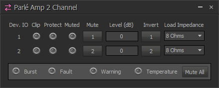
Parlé Amplifier Block
When utilizing the congenital-in, two-channel amplifier of the TCM-1A or TCM-XA, a two-channel amplifier output cake will exist added to the layout. This provides controls to set load impedance, level, and mute, as well every bit monitor the amplifier'southward electric current state.
Of item interest is the Outburst indicator. This is a visual indication that Burst power reserves are existence utilized to handle peaks in the audio point.
Tracking Limits
NOTE: This feature is not available for the TCM-1, TCM-1A, or TCM-1EX.
The azimuth tracker provides the power to restrict beam tracking within zones of the microphone'southward coverage area. The outer edge of the azimuth tracker is divided into multiple segments with a different colour for each axle. Each segment is divided into an arc of 45-degrees that can be enabled or disabled to restrict beam tracking in this area. The azimuth tracker is oriented as if you are looking at the microphone from the top downwardly and the small arrow at the lesser represents the location of the Biamp Logo on the microphone. The color-coded arcs are switches and tin be turned off to prevent the beam from tracking to noises in that surface area. Beam segments are turned on or off by clicking on the arc segment and are black when turned off.
The images beneath illustrate a utilise case where a beam segment might exist disabled to forestall tracking to noises entering a room through a door opening.
![]()
![]()
The next instance illustrates a utilize case where the TTM-X microphone is placed at the end of a small conference table. In this case, you exercise non want beams agile in the areas pointing to the wall brandish.
![]()
![]()
Beamtracking Setup Utilities
NOTE: These features are not bachelor for the TCM-1, TCM-1A, or TCM-1EX.
The azimuth tracker provides access to two useful setup utilities incorporated in the Parlé microphones. These utilities modify the behavior of the microphone'south LED band.
None
When selected, the LED band will behave in accordance with the setting in the initialization dialog. Information technology volition either follow the behavior of the microphone mute within the cake or it is dictated by the state of the logic input nodes for LED control. The Segments and Demo Beams modes operate on a timer and the setting will resort to None subsequently a period of one hr.
Segments
This mode volition turn off the segments of the LED ring that have been turned off in the azimuth tracker. This feature is beneficial during installation to identify the concrete areas that are currently disabled in the microphone.
Demo Beams
This mode will crusade the individual LEDs in the ring to illuminate around the band to bespeak the position of the bodily beam. This allows yous to picket which beams are on and where they are pointed during arrangement commissioning. Note that there is a gain sharing automixer built in the microphone to mix the audio signals from the iv private beams into a single sound channel. If no beams are gated on, the ring will get dark.
Parlé Amplifier Connections
Parlé amplifiers uses standard category cables (CAT5/6) to simplify integration with Biamp C-IC6 loudspeakers. Both the amplifier and loudspeaker have RJ-45 jacks for quick connection.
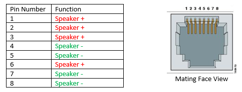
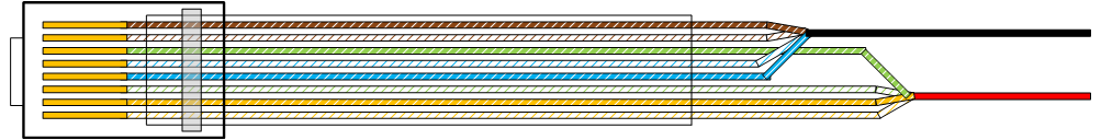
Other loudspeakers can be used with Parlé amps by using the Biamp category cable adapter (CCA) or creating an adaptor using standard True cat cablevision. The connector utilizes pins 1,ii,3, and 6 for speaker (+) and pins 4,v,7, and viii for speaker (-).
Pairs 1 and 4 (Bluish/Dark-brown) are speaker (-) and pairs 2 and 3 (Orange/Dark-green) are speaker (+). Due to this assignment, the resultant connexion volition exist correct regardless of whether T568-A or T-568-B is used. Even a crossover cablevision will end upwardly with the same pairs utilized for speaker (+) and speaker (-).
.
The maximum recommended distance from the Parlé amp to the loudspeaker is 40 meters, or about 130 feet. At this distance in that location will be near 3dB loss at the speaker. However, this is specified with the worst instance scenario of using 26AWG True cat cable.
The below table shows the distance at which there would be just 1dB of loss to the speaker. With 26 AWG CAT cablevision the distance before 1dB of loss is almost 15 meters (l feet). With the Parlé amp mounted near the speaker location, cable lengths are usually shorter than when run back to a rack mounted amplifier in a remote location. Standard CAT-5e cablevision generally uses 24 AWG conductors, which will allow for runs up to 23 meters (75 feet) before a loss of 1dB is incurred.
| True cat Wire Estimate | 4x Equivalent Gauge | Length (1dB loss to 8Ω speaker) |
| 26 AWG | xx AWG | 46.25 ft. |
| 24 AWG | xviii AWG | 75.09 ft. |
| 23 AWG | 17 AWG | 92.90 ft. |
| 22 AWG | 16 AWG | 119.3 ft. |
Please note that at that place is no designation or recommendation made regarding the type of Cat cable to use exterior of wire guess. Shielded cable is Non required. CAT5e or CAT6a will work just fine, just and so will any other standards-based category cable terminated with RJ-45 connectors.
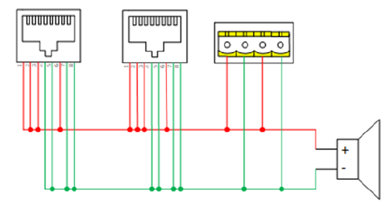
On the Biamp loudspeaker, the RJ-45 and Euroblock / Phoenix connectors are all wired in parallel. Either 1 or a mix of each could be used depending on the requirements of the installation. The Biamp category cable adapter (CCA) is available to convert inline from RJ-45 to Euroblock / Phoenix (female).
Discovery and communications
The Parlé series microphones are Audio Expander-grade devices. This means that they crave a Server-class device (TesiraSERVER, TesiraSERVER-IO, or TesiraFORTÉ) to be present in society for them to exist discoverable and manageable in Tesira software. Unlike other sound expander devices, Parlé microphones are not assigned an IP address for command communications. AVB'due south AVDECC (Sound Video Discovery, Enumeration, Connexion management, and Control) protocol is utilized for this.
Parlé microphones still attach to Tesira's discovery and communications rules that other audio expander devices crave. This means that AVB devices must still be correctly configured to operate in either converged or separated mode.
A common organization design utilizing a Parlé microphone includes a single Server-class device, such every bit the TesiraFORTÉ VT4, with the microphone directly connected to the TesiraFORTÉ VT4's AVB port through a PoE+ injector. Since the AVB and Control networks are physically separated, this setup will require separated networks to exist enabled on the Server-class device in order for it to find and communicate with the microphone.
Delight reference the essential rules for implementing separated networks to ensure success in configuring device discovery and communications. In separated network style, the AVB and Control IP addresses must exist in different subnets. If the microphone does non appear in Remote Devices, double-check to verify that the port IP addresses are not in disharmonize with these rules.
Device Count
The following device count limits use to all Tesira systems running firmware version 3.5 or newer:
- Each SERVER or SERVER-I/O can act as the proxy for upwardly to 24 expander devices in systems that include the TCM-X, TCM-XA, TTM-10, TCM-1, TCM-1A, AMP-450P or EX-UBT.
- Each TesiraFORTÉ can human activity as the proxy for up to 12 expander devices in systems that include the TCM-X, TCM-XA, TTM-X, TCM-1, TCM-1A, AMP-450P or EX-UBT.
- Additional details on arrangement device limits can be constitute in the System Limits section of Tesira Assistance.
Annotation: TCM-XEX, TTM-XEX, and TCM-1EX microphones do not count against the total expander device counts. For example, a TCM-1A with ii TCM-1EX microphones continued should be considered ane expander device (TCM-1A) when making device count considerations.
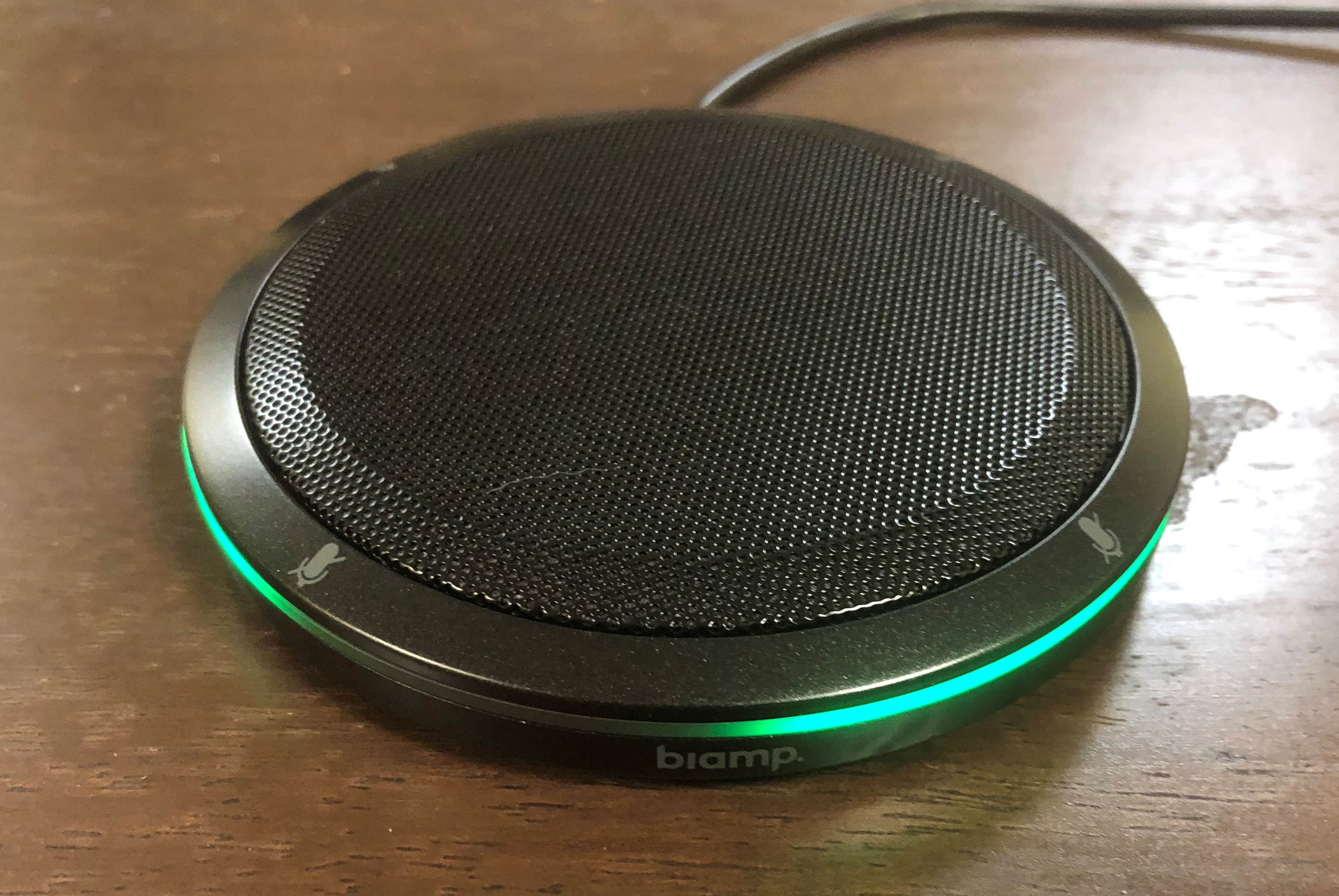
Parlé status LEDs
The TCM-10, TCM-XA, TTM-X, TCM-one, and TCM-1A network boxes, every bit well as the microphone arrays themselves, accept LEDs that provide the current status of the device(s). Below is a list of the various LED behaviors and what they betoken.
| Network Box Condition | LED Indicator |
|---|---|
| No Power | Off |
| Booting/Self-Exam | Red Solid |
| Ready to receive configuration or updating firmware | Yellow Solid |
| Configured and ready to participate in the organization | Green Solid |
| Unit is in Locate mode | Green Flashing |
| Unit has a Major Alarm | Cherry Flashing |
| Unit has a Minor Alarm | Xanthous Flashing |
| Unit has both a Major & Small-scale Warning | Red & Yellow Flashing |
| Amplifier (TCM-1A and TCM-XA only) Status | LED Indicator |
|---|---|
| No Power | Off |
| Powered | Light-green Solid |
| Amplifier limiter is engaged | Yellow Solid |
| Amplifier is in Locate fashion | Green Flashing |
| Unit of measurement has a Major Warning | Red Flashing |
| PoE+ power is not available or insufficient to power the amplifier - it has been turned off | Carmine & Yellow Flashing |
| Microphone Array Status | LED Indicator |
|---|---|
| No Power or Unit of measurement is not configured every bit function of a system | Off* |
| Unit of measurement is configured and operating unremarkably | Green Solid* |
| Unit is in Locate mode | Dark-green Flashing |
| Microphone is Muted | Ruby-red Solid* |
| Unit of measurement has a Major Alarm condition | Ruddy Flashing |
* The microphone array LED behavior tin be customized using logic in an active Tesira configuration file. In this example, certain LED indications may differ from the expected default. Additional information on customizing LED control tin be found in the next section - Parlé Microphone Array Logic
Parlé installation accessories
A diverseness ofParlé installation accessories are available, including:
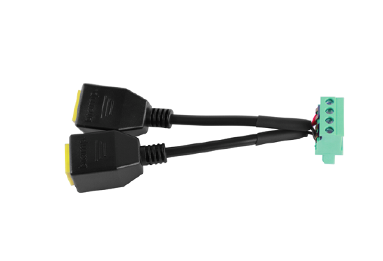
CCA Category Cablevision Adapter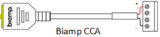
The Biamp CCA is an inline RJ-45 to female person 4-pin 0.2" (v.08mm) pitch Euroblock / Phoenix adapter. A pair can be used to extend any loudspeaker cable using standard category cablevision. The Euroblock connectors can be removed if a category cable to blank wire termination is required. The CCA provides +/- for 1 speaker per category cable. The CCA is applicative to TCM-1A, TCM-XA, AMP-450P, AMP-450BP, and others.
TTM-X-SM Secure Mounting Kit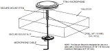
The TTM-Ten-SM Secure Mounting Kit allows permanent installation of the TTM-X mic on tabletops 1.25cm to 5cm (1/two" to two") thick. The kit requires a 16mm (5/8") hole to be drilled through the tabletop for fastener and cable access.
TTM-X 16mm Table Grommet
When a cable access hole for a TTM-X needs to be drilled through a tabletop, the table grommet is recommended to protect cables and provide a clean installation advent. 16mm OD / 7mm ID. (Not required if TTM-X-SM kit is used.)
TCM-X Installation Tool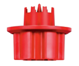
The TCM-X installation tool is a user-friendly hand-driven hole saw sized perfectly for TCM-Ten mic installation in ceiling tiles. It cuts a 35mm pigsty for the mic's threaded stem.
TCM-10-FM Flush Mount Kit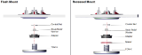
The plenum rated TCM-X-FM Flush Mountain Kit allows users to install the TCM-X mic recessed into the ceiling tile or drywall for a depression profile appearance. The kit supports two LED viewing angles: Flush mount = 130° viewing angle; the addition of an included spacer backside the mic (recessed mount) brings the LED ring flush with the surface for amend visibility at a altitude. Recessed mount 170°. Mic response is unchanged from standard installation in either flush mount or recessed mount. The flush mount kit requires a 162mm (vi.38 inches) diameter hole, a layout template is included with the kit. A minimum mountain depth of 64mm (ii.v inches) is required. Tin mountain in ceilings with a thickness of thirteen-24 mm (0.5" - 0.95") using the included C-Ring or 16-25 mm (0.625" - 1") if using an optional TB-ane ceiling tile span.
TCM-X-DK Drywall Kit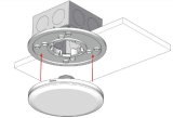
The TCM-X-DK allows for mounting the TCM-X on to a standard electrical back box.
TB-one Ceiling Tile Bridge
Ceiling Tile Bridge suitable for mounting the TCM-one, TCM-1A, TCM-1EX, TCM-10, TCM-XA, TCM-X-FM in locations which require tile span supports.
Seismic Cable Adapter
The seismic cable adapter for is available for all in-ceiling Parlé TCM plenum boxes, besides equally TCM-X mic elements.
fredericksvizienteling.blogspot.com
Source: https://support.biamp.com/Tesira/Parle_microphones/Parl%C3%A9-series_Beamtracking_Microphones
0 Response to "Tcm Readiness Code Must Be Generated Again"
Post a Comment